This group is about reading schematic diagrams. A schematic is an electrical diagram that uses standard component symbols to show how parts are connected. The exam gives you three figures and asks you to identify symbols, so recognizing the common ones is the main skill.
What schematics show
A schematic shows components and their electrical connections. It does not show wire lengths, the physical appearance of parts, or their actual layout on a board. Two circuits that look very different on a bench can have the same schematic. Only the connections are accurately represented.
Common symbols
- Resistor: a zigzag line.
- Variable resistor or potentiometer: a zigzag line with an arrow through it or an arrow touching it.
- Capacitor: two parallel plates, or one straight and one curved plate (on polarized types the curved plate is the negative side). A variable capacitor has an arrow through the plates.
- Inductor: a series of loops or humps. A variable inductor has an arrow through or along the coil.
- Transformer: two coils side by side, usually with parallel lines between them.
- Diode: a triangle pointing at a bar (anode to cathode). An LED adds small arrows leaving the symbol. A Zener diode has a bent bar end.
- Transistor: a circle or lines with a base, plus collector and emitter, the emitter marked with an arrow.
- Battery: alternating long and short parallel lines.
- Lamp: a small bulb or circle shape.
- Fuse: a rectangle with a line through it.
- Switch: a blade that touches or lifts from a terminal.
- Antenna: a vertical line ending in a triangle or fork.
- Ground: a vertical line ending in a short horizontal bar with three slanted lines below it, as in the exam figures.
Figure T-1: transistor lamp circuit
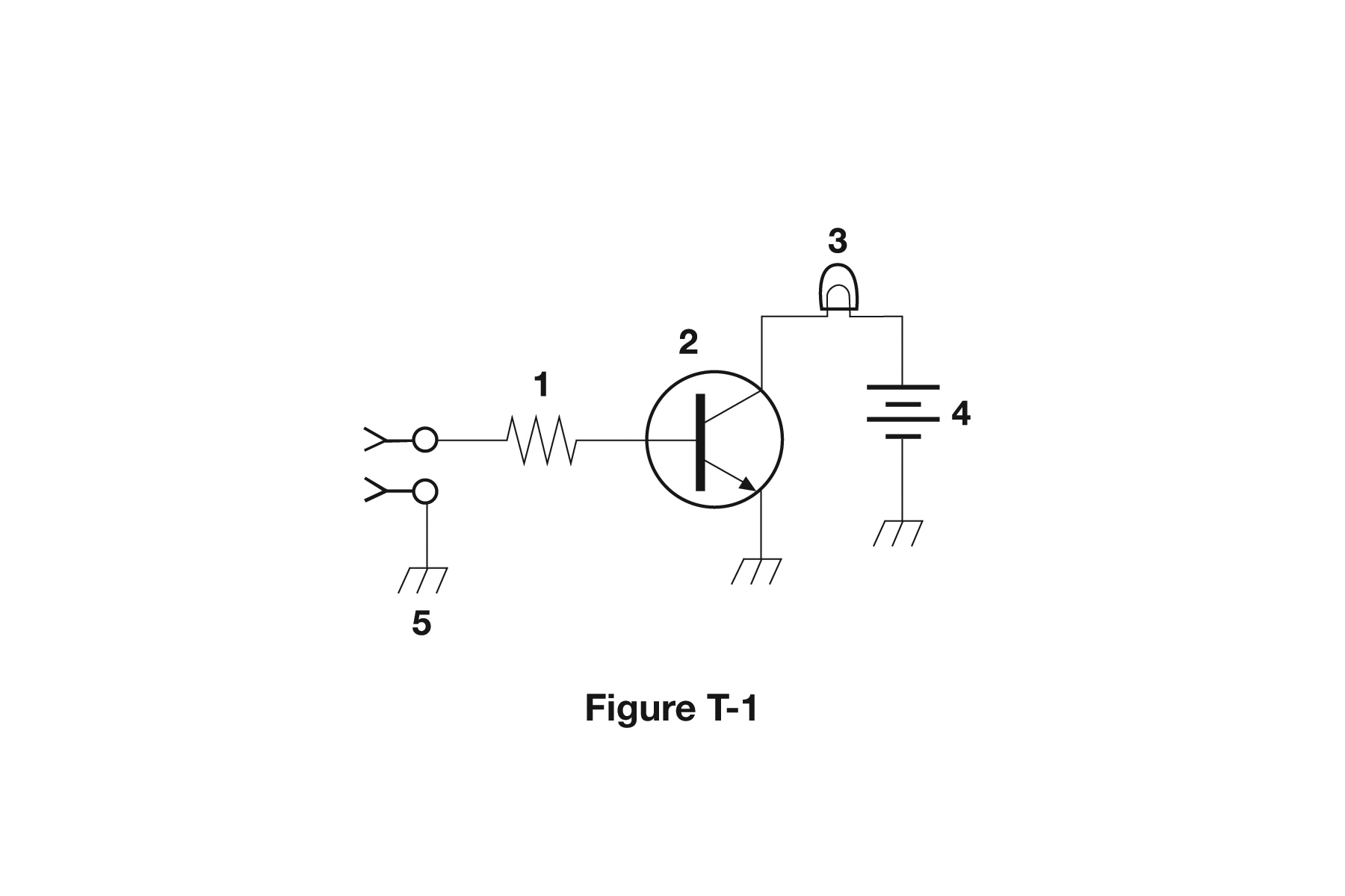
Figure T-1 is a transistor controlling a lamp. Component 1 is the resistor, a zigzag in series with the input. Component 2 is the transistor, a circle containing the vertical base bar with collector and emitter leads. Component 3 is the lamp, drawn as a small rounded bulb shape. Component 4 is the battery, drawn as alternating long and short plates. Component 5 is a ground symbol.
Figure T-2: power supply
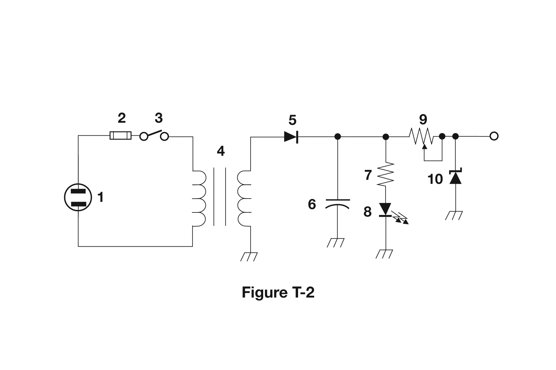
Figure T-2 is a simple power supply. Component 1 is the AC source, 2 is a fuse and 3 is a switch. Component 4 is the transformer, two coils with parallel lines between them. Component 5 is a diode (the rectifier). Component 6 is a capacitor, with one straight and one curved plate, that smooths the output. Component 7 is a resistor feeding component 8, an LED, shown as a diode symbol with arrows pointing away. Component 9 is a variable resistor, a zigzag with an arrow, and component 10 is a Zener diode.
Figure T-3: antenna tuner
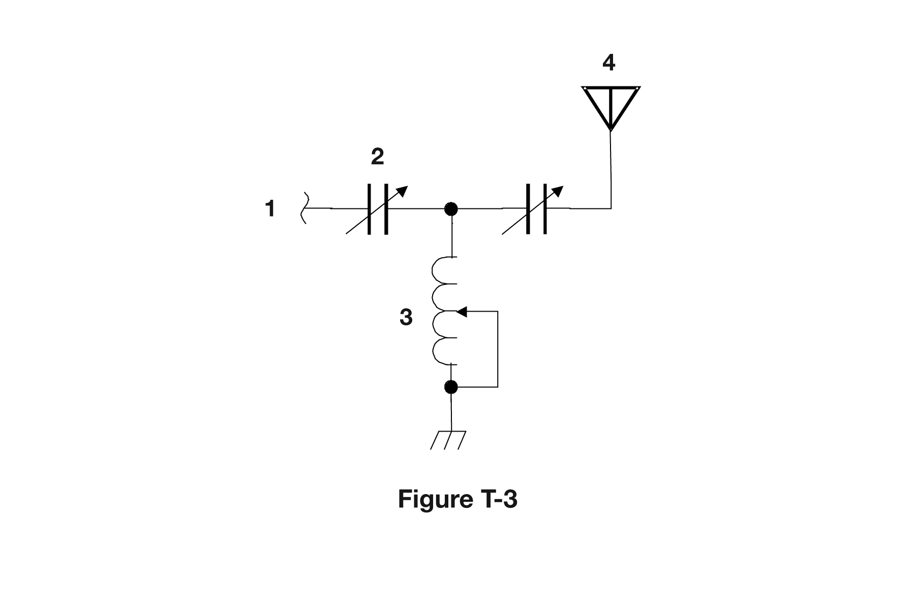
Figure T-3 is an antenna matching network. Component 1 is the input from the transmitter. Component 2 is a variable capacitor, drawn with two plates and an arrow through them. Component 3 is a variable inductor, a coil with an arrow tap. Component 4 is the antenna, a vertical line ending in a triangle.
The arrow idea is key: an arrow across any symbol means it is adjustable. Which part it adjusts tells you the type: plates mean variable capacitor, coil means variable inductor, zigzag means variable resistor.
Key facts to memorize
- Schematic: diagram using standard symbols to show component connections.
- Schematics show connections only, not wire lengths or physical appearance.
- T-1: 1 resistor, 2 transistor, 3 lamp, 4 battery.
- T-2: 3 switch (SPST), 4 transformer, 6 capacitor, 8 LED, 9 variable resistor.
- T-3: 3 variable inductor, 4 antenna.
- An arrow through a symbol means variable.
Memory hooks
- Zigzag = resistor. Loops = inductor. Plates = capacitor. Arrow = adjustable.
- LED = diode with light arrows leaving.