This group connects components to the jobs they do in a radio or power supply: rectifying, switching, regulating, measuring, indicating and tuning. It also covers integrated circuits, transformers, resonant circuits and shielded wire.
Rectifiers
A rectifier changes alternating current (AC) into a varying direct current (DC) signal. Rectifiers are usually built from diodes, which pass current in only one direction. The result is pulsating DC, which a filter capacitor then smooths in a power supply.
Transformers
A transformer is made of two or more coils (windings) that share a magnetic field. It changes AC from one voltage to another, such as stepping 120 V AC down to a lower voltage for a power supply. It only works with AC. A transistor, diode or variable capacitor does not change AC voltage levels.
Relays
A relay is an electrically controlled switch. A small current through an electromagnet coil moves contacts, letting one circuit control another. Relays can switch high currents or isolate circuits, and many radios use them to switch between receive and transmit. A relay is not an amplifier.
Voltage regulators
A regulator is the circuit that controls the amount of voltage from a power supply. It holds the output at a steady value even when load or input changes. This differs from a filter (which smooths ripple) or an oscillator (which creates a signal).
Meters
A meter displays an electrical quantity, such as voltage, current or power, as a numeric value or a needle position. A potentiometer adjusts resistance, a transistor amplifies or switches, and a relay switches.
Indicators
An LED is commonly used as a visual indicator because it lights when current flows through it. FETs and Zener diodes are not designed to emit light, so “all of the above” does not apply to them.
Integrated circuits
An integrated circuit (IC) combines many semiconductors and other components into one package. A voltage regulator IC is a common example. A transducer converts one form of energy to another, a multi-pole relay is a switch, and a transformer is a coil assembly.
Resonant circuits
A resonant or tuned circuit is made by combining an inductor and a capacitor, in series or parallel. Energy sloshes between the capacitor’s electric field and the inductor’s magnetic field, and the circuit responds strongly at one frequency set by the two values. Resistors, Zener diodes and potentiometers are not what is combined with an inductor to make a resonant circuit. A linear regulator, a resistor load for reducing SWR and a high-fidelity audio circuit are not tuned circuits.
Shielded wire
Shielded wire has a conductive covering around the inner conductor. Its purpose is to prevent coupling of unwanted signals to or from the wire. It keeps RF from entering sensitive wiring and keeps signals from radiating out. It does not lower DC resistance or increase current capacity. Shielding by itself does not cure receiver overload.
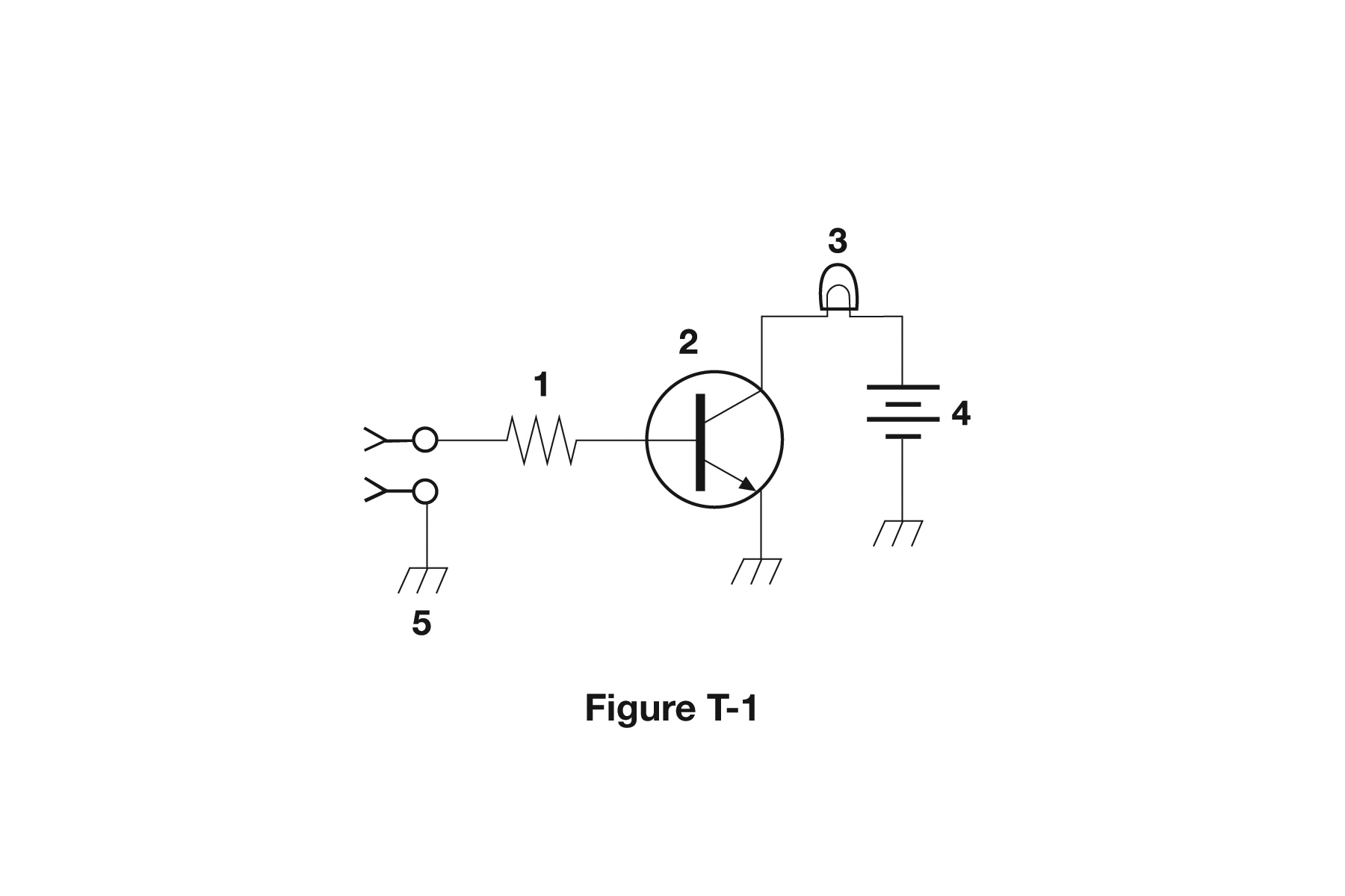
Back to Figure T-1
The transistor, component 2 in Figure T-1, controls the flow of current. The small signal from the input drives the base, and that determines how much current flows through the lamp in the collector circuit.
Key facts to memorize
- Rectifier: converts AC into varying (pulsating) DC.
- Relay: electrically controlled switch.
- Regulator: controls the voltage from a power supply.
- Transformer: changes AC voltage, such as 120 V AC to a lower value.
- Meter: shows a quantity as a numeric value.
- LED: common visual indicator.
- Integrated circuit: many semiconductors and parts in one package.
- Resonant circuit: inductor plus capacitor, in series or parallel.
- Shielded wire: prevents unwanted signal coupling to or from the wire.
- Figure T-1 component 2 (transistor): controls the flow of current.
Memory hooks
- LC = resonance: an Inductor and a Capacitor make a tuned circuit.
- Rectifier “makes it right”: AC goes in, one-direction current comes out.